|
Size: 18221
Comment:
|
Size: 18283
Comment:
|
| Deletions are marked like this. | Additions are marked like this. |
| Line 1: | Line 1: |
| #acl apw185:read,write,delete Known:read All: | ## page was renamed from ajm/orient/display #acl +All:read apw185:read,write,delete Known:read All: |
| Line 7: | Line 8: |
| * [[ajm/orient|The Orient Program]] | * [[ajm/orient/start|The Orient Program]] |
| Line 120: | Line 121: |
| * ...we import a grid file that contains the electrostatic energies calculated using the [[ajm:camcasp:energy-scan-display|ENERGY-SCAN module in CamCASP.]] | * ...we import a grid file that contains the electrostatic energies calculated using the [[ajm/camcasp/energy-scan-display|ENERGY-SCAN module in CamCASP.]] |
| Line 367: | Line 368: |
| ===Differences: On-the-fly=== | === Differences: On-the-fly === |
| Line 469: | Line 470: |
| [[attachment: formamide_difference_map.ornt]] | [[attachment:formamide_difference_map.ornt]] |
Navigation:
Orient: Using the Display : Orient version >= 4.9
Warning
In progress!!!
The Orient program can be used to create 3D maps of energies or other quantities mapped onto a surface. These can be scalar or vector maps. Here we will look into using scalar maps.
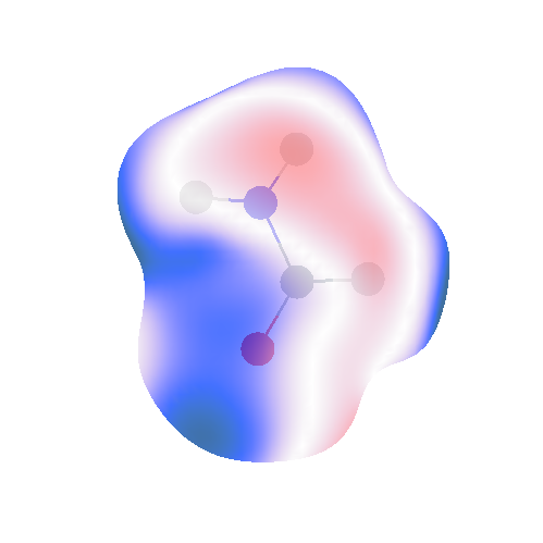
The idea is to create something that looks like this:

In this map, I have visualised the difference in the electrostatic potential arising from a rank 0 (charge only) multipole model (from the ISA) against a reference potential from SAPT(DFT). Actually, rather than calculate a potential, I have calculated the electrostatic energy between either the charge model or actual density of formamide and a unit point charge. This point charge has been placed at various points on a 0.001 a.u. isodensity surface. Orient allows us to visualise the errors made by the point charge model. This is only one view of an image that can be rotated/moved around using a mouse.
Consider what we need to make such an image:
- molecular geometry
- multipole model
- reference energies/potential
- surface map (triangulated)
- Orient input file for the display
We will usually have the first two so let's consider the others here.
Generating the display data using CamCASP
The CamCASP program can be used to generate an isodensity surface using the Display module. And then the ENERGY-SCAN module can be used to calculate the reference energies for this surface. Instructions are here.
Orient input file for display
Let's start with the Orient file for display as its requirements will become clearer once you see it. The input files used below have been created from an Orient display file generated using the Cluster program.
Display pre-computed reference energies
Here's the input file for displaying a reference energy already calculated, in this case, using the DISPLAY and ENERGY-SCAN modules in CamCASP:
formamide-display-reference.ornt
! ORIENT display commands

UNITS BOHR

Parameters
      Sites     13 polarizable     11
      S-functions 50000
      Alphas 50000
      Parameter-sets 50000
      Pairs 100000
End

Types
      C          Z     6
      O          Z     8
      N          Z     7
      H1         Z     1
      H2         Z     1
      H3         Z     1
End

Molecule  formamide at  0.0 0.0 0.0
  ! Units BOHR
  C           0.73690219   -0.29016270    0.00000000   Type C
  O          -0.41965533   -2.26421099    0.00000000   Type O
  N          -0.33761508    2.03824113    0.00000000   Type N
  H1          2.82092994   -0.20596490    0.00000000   Type H1
  H2         -2.23332780    2.19617606    0.00000000   Type H2
  H3          0.72278745    3.61139057    0.00000000   Type H3
  ! #include HCONH2_DMA2_L4.mom
End
Edit formamide
   ! #include formamide.axes
   Bonds Auto
End

Units Bohr kJ/mol

! This is a probe of the induction energy
Atom X at 0.0 0.0 0.0 rank 0
  Q00 =  1.0

End

! Not yet tested

Display
  Import Map HCONH2_1.5vdW_ISA_L4L4_ref.grid  ISA-1.5vdW

  Colour-map
    0   210  0.25  1
    6   240  0.75  1
   12   300  1.0   0
   18   360  0.75  1
   24   390  0.25  1
  End
  Show ISA-1.5vdW
    Viewport 08
    Colour-scale min -200 max +200 top +200
    Ball-and-stick
  End
End

Finish
Points to note:
- No multipoles included because...
...we import a grid file that contains the electrostatic energies calculated using the ENERGY-SCAN module in CamCASP.
Also, we have commented out the lines in Display energy that calculate a grid using the atomic van der Waals radii. Once again, this is because the grid is included in the file we imported.
The import from file formamide_1.00E-03_iso_aQZ_Q.elst is done with values. This tells Orient to import energy values at each point.
In this calculation, the probe molecule X does nothing.
You need to adjust the Viewport (distance at which you are viewing the molecule) and Colour-Scale to something appropriate.
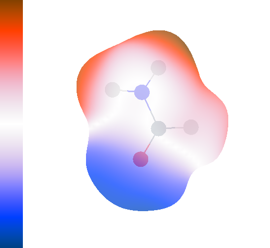
Run this using Orient compiled with OPEN_GL and you will see something like this:

The Orient output should look like this:
$ orient <
             ORIENT version 4.8.15  29 May 2014

                             by

                        Anthony Stone

...

Molecule 1 (Site 1):  formamide
Origin position (cartesian) 0.00000 0.00000 0.00000

Site 2:  C    Type C
Position (cartesian) 0.73690 -0.29016 0.00000

...

Preparing display:  formamide...Q 1.0 elst
Importing grid and values from file formamide_1.00E-03_iso_aQZ_Q.elst
4704 points and 9404 triangles read from file formamide_1.00E-03_iso_aQZ_Q.elst
Displaying values read from file formamide_1.00E-03_iso_aQZ_Q.elst
Minimum energy =   -174.19700 kJ/mol
Maximum energy =    204.53000 kJ/mol
Colour scale:
  bottom   -200.00000 kJ/mol
  top       200.00000 kJ/mol
4704 points,  9404 triangles
The code prints out the Minimum and Maximum energies encountered. Use these values to set the range of the energy scale using the Colour-scale command.
Display using van der Waals surfaces
It is also possible to generate a display within Orient, using the van der Waals surfaces for each atom to create a molecular surface. Orient has default radii for each atom, but they can be set manually (see the Orient manual). Here we use the standard radii. Here's the input file:
formamide-display-vdWsurface.ornt
! ORIENT display commands

UNITS BOHR

Parameters
      Sites     13 polarizable     11
      S-functions 50000
      Alphas 50000
      Parameter-sets 50000
      Pairs 100000
End

Types
      C          Z     6
      O          Z     8
      N          Z     7
      H1         Z     1
      H2         Z     1
      H3         Z     1
End

Molecule  formamide at  0.0 0.0 0.0
  #include formamide_aQZ_B+DF_z0.1_aQZset2_L4.mom
End
Edit formamide
   ! #include formamide.axes
   Bonds Auto
End

Units Bohr kJ/mol

! This is a probe of the induction energy
Atom X at 0.0 0.0 0.0 rank 0
  Q00 =  1.0

End

Display
  Grid
    Name 1.5vdW
    Title "Elst : ISA L4"
    Molecule formamide
    Smoothed  0.5
    Step  0.75 B
    Radius scale 1.5  Add 0.0
  End
  Map Pot-1.5vdW
    Molecule formamide
    Title "Elst map of potential"
    Potential
  End
  Colour-map
    0   210  0.25  1
    6   240  0.75  1
   12   300  1.0   0
   18   360  0.75  1
   24   390  0.25  1
  End
  Show Pot-1.5vdW
    Viewport 08
    Colour-scale min -200 max +200 top +200
    Ball-and-stick
  End
End

Finish
Points to note:
We now need a multipole moment file. I've used an ISA calculation and the multipole moments can be found in formamide_aQZ_B+DF_z0.1_aQZset2_L4.mom.
The surface is a 1.5 x vdW surface. The 1.5 is set using the Radii command.
Step 0.75 B sets the quality of the surface by defining the size of the triangle edges, in this case, in Bohr.
Grid Exp defines the kind of grid. See the Orient manual for details.
- This time the range of energies is smaller as we have no penentration contribution in this calculation.
- Also, the shape of the surface is quite different from the 0.001 a.u. isodensity surface shown above.
Difference maps using Orient
Now we know how to display energies, but what about differences in energies||width= We often want to compare two models: say, the rank 0 multipole model may need to be compared with SAPT(DFT) or, perhaps more appropriately, with a rank 4 model. How to we do this||width=
The idea here is to import a grid with values (as we did with the SAPT(DFT) reference above) and use it as a REFERENCE. We then compare the energies calculated with a model against these values. Orient will plot the difference. Here's an input file for a comparison against pre-computed SAPT(DFT) electrostatic energies:
Warning
Need to be updated
formamide-compare-against-sapt.ornt
! ORIENT display commands

UNITS BOHR

Parameters
      Sites     10 polarizable      8
      S-functions 50000
      Alphas 50000
      Parameter-sets 50000
      Pairs 100000
End

Types
      C          Z     6
      O          Z     8
      N          Z     7
      H1         Z     1
      H2         Z     1
      H3         Z     1
End

Molecule  HCONH2 at  0.0 0.0 0.0
    #include formamide_aQZ_B+DF_z0.1_aQZset2_L4.mom
End
Edit HCONH2
   Bonds Auto
   Limit Rank 0 for sites C O N
   Limit Rank 0 for sites H1 H2 H3
End

Units Bohr kJ/mol

! This is a probe of the induction energy
Atom X at 0.0 0.0 0.0 rank 0
  Q00 = +1.0

End

Display energy
  Title "HCONH2...Q 1.0 Elst "
  Molecule HCONH2
  ! * Use the Compare line for energy comparisons and
  ! * comment out the Radii, Step and Grid lines
  Import formamide_1.00E-03_iso_aQZ_Q.elst Reference
! Radii scale 2.0
! Step 0.75 B
! Grid exp
  Colour-map
    0   210  0.25  1
    6   240  0.75  1
   12   300  1.0   0
   18   360  0.75  1
   24   390  0.25  1
  End
  Viewport 08
  Colour-scale min -30 max +30 top +30
  Probe X
  Ball-and-stick
  ! * Uncomment the following line for the grid:
  ! Write HCONH2_2vdW.grid no values
End

Finish
Points to note:
- We need a multipole model.
We have used the LIMIT option to reduce the rank of the model, in this case, from rank 4 on all atoms, to rank 0 on the hydrogen atoms and rank 0 on the heavier atoms. You could make any model truncation you need.
Import the reference values using Import formamide_1.00E-03_iso_aQZ_Q.elst Reference. The Reference command tells Orient that everything will be compared against the energies in this file.
The Radii, Step and Grid commands are commented out as the Import command reads the grid along with the reference values.
- Since we will be displaying differences, reduce the energy scale.
As usual, Orient will print out a summary when you run it. Here's the tail end of the output containing the relevant details:
Preparing display:  HCONH2...Q 1.0 Elst
Importing grid and values from file formamide_1.00E-03_iso_aQZ_Q.elst
4704 points and 9404 triangles read from file formamide_1.00E-03_iso_aQZ_Q.elst
Displaying calculated values
Maximum difference =     14.13234 kJ/mol
Minimum difference =    -39.17835 kJ/mol
r.m.s. difference  =     14.57066 kJ/mol
average difference =     -7.47084 kJ/mol
Standard deviation =     12.51095 kJ/mol
Colour scale:
  bottom    -30.00000 kJ/mol
  top        30.00000 kJ/mol
4704 points,  9404 triangles
The max and min differences are reported and may be used to determine the energy diference scale needed. Additionally Orient prints out the r.m.s. and average differences.
Differences against references calculated with Orient
What if we want to compare a rank 0 multipole model against a rank 4 model||width= Or the DMA multipoles against the ISA multipoles||width= In these cases, we might want to define a reference using the ISA rank 4 multipoles. Once we have this reference, we could use the above method to compare any other multipole model against the reference.
In Orient 4.9 the reference can be calculated on the fly. There is the possibility of pre-calculating the reference but this route seems to be buggy at present. So we will tackle the on-the-fly case now:
Differences: On-the-fly
To do this we need to define two instances of the molecule of interest:
- - formamide-ref : will be the reference molecule with multipoles up to rank 4 - formamide : this will be the molecule to be tested. It will have a different set of multipoles. Perhaps one with a lower rank the formamide-ref, or just a completely different set.
Important
formamide and formamide-ref must have the same geometry!
Here is the Orient code for these two:
Molecule  formamide-ref at  0.0 0.0 0.0
  #include formamide_aQZ_B+DF_z0.1_aQZset2_L4.mom
End
Edit formamide-ref
   Bonds Auto
   Limit rank 4 for H1 H2 H3
   Limit rank 4 for C O N
End


Molecule  formamide at  0.0 0.0 0.0
  #include formamide_aQZ_B+DF_z0.1_aQZset2_L4.mom
End
Edit formamide
   Bonds Auto
   Limit rank 0 for H1 H2 H3
   Limit rank 0 for C O N
End
Now for the display commands:
- - Grid: First we will use formamide-ref to define the grid. - Map: Then we will use the MAP function to create a reference potential calculation on this grid. This will use formamide-ref. - Map: And once again use the MAP function, this time for molecule formamide. - Map Difference: We will use a third MAP function to take the difference in the previous maps. - Colour: Define the colour map. - Show: And finally display the difference map. - Describe: Use this function to print out some information about the map. This is particularly useful for difference maps.
The commands to do this are:
Display
  ! Generate the grid around one of the formamide molecules
  Grid
    Name 1.5vdW
    Title "Elst : ISA L4"
    Molecule formamide-ref
    Smoothed  0.5
    Step  0.75 B
    Radius scale 1.5  Add 0.0
  End
  ! And the potential on this grid for the reference formamide
  Map L4-1.5vdW
    Molecule formamide-ref
    Title "Elst map of potential"
    Potential
  End
  ! And the potential on the same grid for the test formamdie
  Map Ln-1.5vdW
    Molecule formamide
    Title "Elst map of potential"
    Potential
  End

  ! Now take the difference of the two:
  Map Diff
    Molecule formamide
    Title "Diff Elst map of potential"
    Difference L4-1.5vdW minus Ln-1.5vdW
  End

  ! Write out some useful information about the difference map:
  Describe Map Diff

  Colour-map
    0   210  0.25  1
    6   240  0.75  1
   12   300  1.0   0
   18   360  0.75  1
   24   390  0.25  1
  End

  ! And finally, display the difference map:
  Show Diff
    Viewport 08
    Colour-scale min -30 max +30 top +30
    Ball-and-stick
  End
End
Here is the entire file for a difference map calculation:
! ORIENT display commands

UNITS BOHR

Parameters
      Sites     50 polarizable     11
      S-functions 50000
      Alphas 50000
      Parameter-sets 50000
      Pairs 100000
End

Types
      C          Z     6
      O          Z     8
      N          Z     7
      H1         Z     1
      H2         Z     1
      H3         Z     1
End

Molecule  formamide-ref at  0.0 0.0 0.0
  #include formamide_aQZ_B+DF_z0.1_aQZset2_L4.mom
End
Edit formamide-ref
   Bonds Auto
   Limit rank 4 for H1 H2 H3
   Limit rank 4 for C O N
End


Molecule  formamide at  0.0 0.0 0.0
  #include formamide_aQZ_B+DF_z0.1_aQZset2_L4.mom
End
Edit formamide
   Bonds Auto
   Limit rank 0 for H1 H2 H3
   Limit rank 0 for C O N
End

Units Bohr kJ/mol

Display
  ! Generate the grid around one of the formamide molecules
  Grid
    Name 1.5vdW
    Title "Elst : ISA L4"
    Molecule formamide-ref
    Smoothed  0.5
    Step  0.75 B
    Radius scale 1.5  Add 0.0
  End
  ! And the potential on this grid for the reference formamide
  Map L4-1.5vdW
    Molecule formamide-ref
    Title "Elst map of potential"
    Potential
  End
  ! And the potential on the same grid for the test formamdie
  Map Ln-1.5vdW
    Molecule formamide
    Title "Elst map of potential"
    Potential
  End

  ! Now take the difference of the two:
  Map Diff
    Molecule formamide
    Title "Diff Elst map of potential"
    Difference L4-1.5vdW minus Ln-1.5vdW
  End

  ! Write out some useful information about the difference map:
  Describe Map Diff

  Colour-map
    0   210  0.25  1
    6   240  0.75  1
   12   300  1.0   0
   18   360  0.75  1
   24   390  0.25  1
  End

  ! And finally, display the difference map:
  Show Diff
    Viewport 08
    Colour-scale min -30 max +30 top +30
    Ball-and-stick
  End
End

Finish
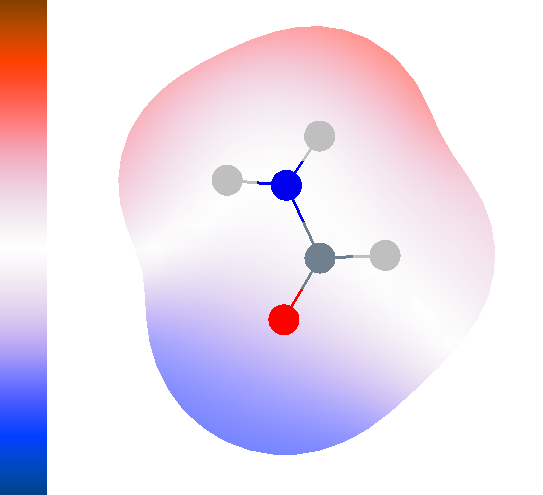
Try this out with different ranks for the multipoles on molecule formamide. You should get an output like:
             ORIENT version 4.9.04  03 Aug 2016

                             by

                        Anthony Stone

...
...
Target grid spacing = 0.7500 bohr

Finding smoothed surface grid
1150 points, 2296 triangles
Minimum potential  =     -1.26422 V  (    -0.04646 a.u.)
Maximum potential  =      1.12788 V  (     0.04145 a.u.)
Minimum potential  =     -1.36323 V  (    -0.05010 a.u.)
Maximum potential  =      1.10025 V  (     0.04043 a.u.)
Minimum potential  =     -0.14260 V  (    -0.00524 a.u.)
Maximum potential  =      0.10640 V  (     0.00391 a.u.)

Map 3: Diff
Grid 1.5vdW
Defined T, Scalar T,  vector F
Molecule 2 formamide
Step  0.750
1150 points
Minimum scalar value  -13.75879 kJ/mol,        maximum   10.26584 kJ/mol
R.m.s. difference =   6.12867 kJ/mol
Colour scale:
  bottom    -30.00000 kJ/mol
  top        30.00000 kJ/mol
Entering show_map