Contents
Navigation:
BOE Bot
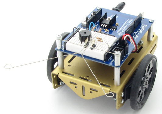
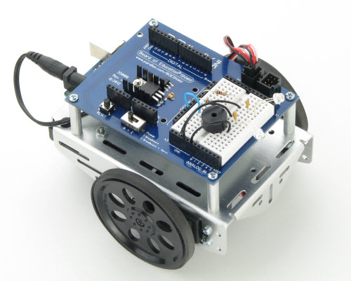
The Board Of Education robot (BOE Bot) is an Arduino-based self-navigating robot that can be constructed to sense the world with touch, visible light and infrared light. You can make it navigate mazes, detect edges, follow paths and detect and follow other BOE Bots. Have a look at the following examples on Youtube:
Here's the simplest version of the robot: Navigation with whiskers.
Here we have two robots: one following the other. They use IR light and sensors for detection.
Aims of the experiment
Today much of science and technology relies on using computers to process and make sense of large bodies of data. This often requires a knowledge of programming languages like C, C++ and Python. But programming on its own can be intimidating and even (to some) boring. In this cool experiment we will combine hands-on electronics and robotics with programming to actually see the results of our programs.
You will learn how to use and program the Arduino microcontroller which forms the brains of the BOE Bot. The Arduino is a simple but powerful microcontroller that can accept various forms of input (from sensors) and process the inputs (using the program - this is where you come in) to produce outputs (that is, control the robot).
By the end of the experiment you will know how to use and program the Arduino, the basics of electronics (resistors, diodes, photo transistors) and will know enough to get you going onto your own projects.
Assessment
The assessement of this experiment is rather different from any of the others you will have done in the SCM laboratory. There is no error analysis or data collection in the usual sense. Instead the focus here is on programming and the development of algorithms to control the robot. Therefore, you will be assessed on
- Your description of the algorithms: this is a high-level description that must be done in the text of the report.
- Comments in the programs that describe what the program is doing.
- A description of the modifications you have made, why you made them, and what their effects (if any) were.
- You will need to describe each stage in the robot's construction and development.
- Each section below includes an Assessment sub-section describing what is essential for your report.
- Each section contains challenges which include questions, exercises and projects. In most cases you will need to do the exercises only. Solutions are also provided, but these are meant as a guide and learning aid. Your solution and description must be made in your own words. Any programs included here must be well commented.
Note
//Should you include programs in your report? //
If you do so, the report will become very long indeed. But you do need to include the important bits of the programs you have used.
//How do you know which bits of the programs to include? //
The parts needed to make your point are all that you need. Do you really need the definitions of all variables? Or the setup() portion? Often not. Often all you will need is to say something along the lines: the following function was used to read out the phototransistors....followed by snippit of the function...and an explanation of how it works.
For an example of how to quote only small portions of the program see the examples on this page. (click here for a PDF version)
Try to be as concise as you can. Remember that the report must be between 8 to 12 pages only!
Important
Structure of your report: Your report should be broadly structured as follows:
Theory: There is no theory as such. This is a programming exercise, so your Theory section should describe the elements of programming that you have learnt during the course of this experiment. Use short snippets of code to illustrate the different structures. Start from the overall structure of an Arduino sketch.
Experimental setup: This would include the Arduino, the BOE bot, and related circuits.
Results: These would include the data you have been asked to record below. But unlike the other experiments you have done, you are expected to describe the working of some programs.
Error Analysis: There is none. Instead the marks usually allocated to this will be distributed to the Results section.
Conclusions: This I leave to you. What was this experiment all about? What happened? What did you learn? What were the results of the exercises? Where do you see this lead? What's the point of programming in the context of a Physics laboratory? What are the applications of microcontrollers? What are the strengths and limitations of the Arduino? These are only some questions you will want to consider. No doubt you will find others.
The BOE Bot
We will be partially assembling your BOE Bot. Yes, it is more fun assembling it on your own, but we don't have time for everything. So what you should see is something like the BOT on the right (but without the LEDs and resistors):
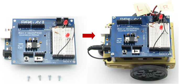
The Arduino board hangs under the BOE shield (add-on boards to the Arduino are called //shields// - perhaps because that is what they do: they shield the microcontroller from the World).
Getting started with the BOE shield
Have a good look at the BOE shield. This is where you will connect all components. It is the board sitting above the Arduino. The shield contains a number of Input/Output (I/O) pins (black) with numbers. Also present is a white //proto-typing// area which is where all the components will go.
We will no go through a series of activities. You must get through these in sequence.
Our first activity will be to build and test the LED indicator lights. We will learn how to use the BOE shield, the breadboard and LEDs, resistors etc. You may already know much of the information on these websites. If so, skip the bits you know, but make sure you do not miss any important steps or exercises.
Next we start to control the servo motors. Since these motors have already been built into the BOE Bot, you will not see the servo //horns// move, but rather, you will see the Bot wheels move. Make sure that the Bot does not roll off the table as this will break it!
All done? Go to the Challenges section and see how you fare. You must do exercise 3. The rest are optional.
Important Assessment
- Brief description of the steps you have taken and the results of this section. Start with the aims of this section.
Solve the three exercises in the Challenges section. Your report should include a detailed description of the third exercise only. This must be in your own words and not a cut-and-paste from the website.
- Include any relevant circuit diagrams and programs. Remember to include comments in your programs.
Assemble and Test the BOE Bot
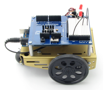
You are nearly ready for some real robotics, but we first need to test the BOE Bot to make sure all is well. The Bot has already been assembled for you, but it has likely not been tested. Make sure you get through all activities in this section before proceeding.
Assembling the BOE Bot (SKIP as we have already done the assembly for you)
Re-test the Servos (a quick test to make sure the servos have been correctly set up)
Test speed control Record and plot the transfer curve data.
All done? Take the Challenge. Solve Exercises 1 and 2.
Important Assessment
- The data table and plot of the transfer curve for the servos.
Warning
You should have finished all parts to this point by the end of week 1. Have you got:
- Data for the transfer curve?
- Notes for the elements of the programs so you can describe the working of the programs?
Navigation
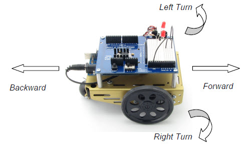
In this section you will learn how to control the BOE Bot using more advanced programming techniques. Work through as many activities as you can (time permitting) and try and understand the programming methods the tutorials explain. By the end of this section you should have a good understanding of functions in C and should be able to get the BOE Bot to maneuver in well-defined ways.
Calculating distances Describe the results of this section in brief.
Ramping Include the code you have used for the ramping procedure. As always, comments are needed!
Using Functions This is a very important section as you will learn how to use functions here. Provide a concise, but clear description of the final code with a description of how functions work.
Custom Maneuver Function Also very important as this function will be used later. Describe how the maneuver function works.
Maneuver with Arrays This will introduce you to arrays.
Done? Go to the Summary and Challenges. Do exercise 3 only.
Important Assessment
- A description (with a commented program) of functions. In particular the maneuver function.
- Include a detailed solution to exercise 3 only. As always, this should include the program and a description (in your own words) of what the program does in each stage.
Maneuver with Tactile Sensors

This is the stage we have been working up to: An autonomous robot capable of moving around and self-navigating.
Go to the Tactile Navigation page and try out all four activities. Links to these are also provided below:
Don't forget the Challenges at the end and do exercises 3 and 4 only.
Did you manage to get your BOE Bot to get out of corners? This is probably the hardest thing to get right. Ever seen insects unable to get out of a window? The BOE Bot behaves like that when in a corner. Play around with the code to build in a bit of atrifical intelligence to make it recognise a corner and get out of one.
Important Assessment
- A description of the robot and how it senses its environment.
- A detailed description of the algorithm used to get out of corners. How does it work? Can you think of a way of improving it?
- Solutions to exercises 3 and 4. Relevant parts of the program and a description.
Warning
You should have finished or almost finished all parts till here by the end of week 2.
Navigation with visible light sensors
Navigation with whiskers is neat but not too exciting. It's like walking around blindfolded, with your arms extended out like the whiskers are. You can get around, but it would be nicer to //see// what's around. This is where the phototransistors come in. They allow the BOE Bot to sense light levels around the room and navigate towards the light, or away from it. It is even possible to get the Bot to circle a light - exactly the way phototactic insects like moths circle ceiling lights.
We will do all the activities in the Photo-Navigation section. These are also listed below.
What is a phototransistor? Make sure you read this.
Activity 1: Navigation with a single phototransistor. Get to the stage where your Bot is able to stop under a bright light. Describe the program and circuit you have used to achieve this. This circuit uses a single phototransistor. You can't use only one for real navigation. Also, the way in which this circuit is designed makes it quite sensitive to the light level in the room. Take it to another room with a different light level and it may not work as expected. The next activity fixes this problem.
Activity 2: Measure light over a large range. This is an important part of this project. Here we use two phototransistors in what is called a //charge-transfer circuit// to allow the Bot to see in a wide range of lighting scenarios.
Activity 3: Measure light levels for roaming. Here we get to use a neat algorithm to use the outputs of the phototransistors to navigate. This will be tested using a graphical display, which is really quite neat!
A light roaming routine. The Bot won't move just yet, but you need to get through this step to see what the sketch does. Test it and try to understand how it works.
Navigation by Light. Finally get the Bot to auto-navigate using light.
Challenges : Solve project 2: get the robot to seek shade rather than light.
Important
Assessment
- Describe how you used a single photo transistor to get the robot to detect light and stop under a bright light. Circuit diagram and program needed.
- How does a charge-transfer circuit work? What are the principles involved? Circuit diagram needed here. How does the program work?
- How do you get the robot to navigate under different lighting conditions? How does the code adapt to differnt conditions? Can you think of any weaknesses in the code?
- Provide an example of a graphical display of the light measurement from the two photo transistors.
- Provide the code you have used to get the robot to navigate with light. Make sure it is well commented. You may provide the code in sections, with textual descriptions of each section.
- Solve project 2: Get the robot to seek shade rather than light. How did you achieve this? Provide a clear explanation.
Tip
- Final Challenge: Navigation with both whiskers and light sensors
Can you now combine the whiskers and phototransistors to allow the robot to navigate with light (using the phototransistors) as well as the whiskers? This is a useful combination when it encounters light reflected off a barrier: the phototransistors alone will cause the Bot to go towards the reflected light, but the whiskers would be able to tell it that it can't get through.
You will need to
- combine the two circuits. Plan it so that all components fit on the small bread board.
combine the two programs: The navigation with whiskers program will need to be combined with the light navigation program. Since this can be tricky, I have put a sample program here. You will find hints included in the program. Feel free to edit it. Bear in mind that this program must be made consistent with the circuit layout you decide upon.
Once you are done, show the result to your lab demonstrator. Take a photo of the setup. If you have modified the program, save a copy and include the relevant portion in your report. Make sure you explain clearly what you have done using suitable comments. The code is long so please do not include all of it and try to keep most of it in an Appendix. As with all programs, you need to explain how it works. This needs to be a high-level, algorithmic description. It should not be too long!
In your lab report you will need to display a clear circuit diagram of the circuit used (this should be the schematic circuit diagram, not a photo of the circuit! You can sketch the circuit diagram and photograph it, but make sure it is a clear and well-labeled sketch.) for the combined whiskers and phototransistor navigation.
Warning
- The assessed part of your lab ends here.
Proceed to the next step (which is optional!) only if you have completed all parts of above, assessed portion!
Navigation with IR
The final stage in the development of the robot is to get it to navigate with infrared light emmitters and sensors. As we shall see, these behave like long-range whiskers. We will now be able to get the robot to detect the edge of a table (risky and will will instead use black take to simulate the edge) and, optionally, to follow another robot around.
If you finish the required parts of this section early, you could attempt to get the robot to navigate a maze (we will have a competition) and perhaps even to follow another robot.
We will attempt all activities in the Navigating with IR section. These are listed here:
Field testing Here we use LEDs to signal the detection (recall that we cannot see in the infrared so we use the LEDs to indicate a detection).
Range-detection measurements Can we control the intensity of the IR light to control the range of the IR detection? Make a table of your measurements. Take multiple measurements to get reliable results.
Object detection and avoidance Notice that this program is very similar to what we had used for navigation with whiskers.
High-performance navigation Here we improve the code to make it more suitable for naviation with the IR LEDs and sensors. This marks the formal end of this laboratory. All other parts are optional and should be attempted only if you have completed all the essential parts!
Drop-off detection Get the robot to detect the edge of a table simulated with black tape. Make sure that you do not test this at the actual table edge!!!
Challenges Attempt project #2.
Tip
Maze navigation
If time permits (and you get to this stage!) we will have a maze navigation competition. This can be tricky. You will need to really understand what your robot is doing to get it to navigate in the confines of a maze.
IR and visible light navigation (optional)
It is possible to combine the IR and visible light navigation codes and hardware. With this, you could make a robot that used visible light to look for bright (or dark) areas, but which switched to IR navigation if obstacles were detected. (This is optional.)
My code for IR and visible navigation is here. You may want to compare codes. Which one is more efficient and robust?
SKIP THIS
The Arduino
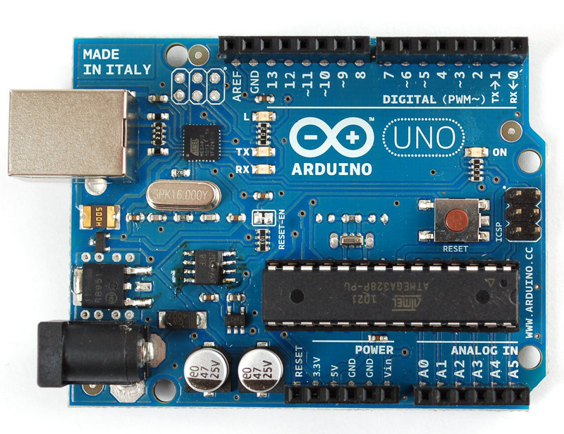
You will first need to learn a little about this microcontroller. This is best done by using it to build a few projects:
There is more information and more ideas for projects on the Arduino page. Additionally, you will find links to the C-language reference and other useful information. So have a look there.
Try to understand what the programs - called //sketches// in Arduino lingo - do and how they achieve the behaviour.
When you are comfortable with those get back the BOE Bot.
Important Assessment
- You do not need to describe these experiments in your report. But you do need to (briefly) describe what an Arduino is and how we communicate with it using I/O pins and a sketch. Don't spend too much time on this. The main aim here is to introduce you to the Arduino and the basic elements of programming this microcontroller.
