Contents
Pendulum : Automated data aquisition
Note
Page created by Navot Arad and edited by Alston
Note
This page is not meant to be comprehensive, but is meant to accompany the Scientific Measurement lab script for the Pendulum experiment.
All that the user needs to change is the variable: **periods**. Default value is 1 (times one period), and this could be increased to time more periods and (hopefully) gain on accuracy.


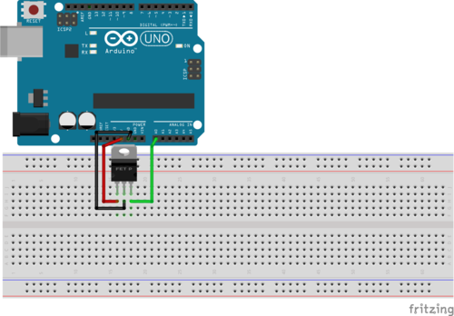
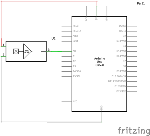
The circuit only has 1 component, the hall sensor. It has 3 pins; pin 1 is connected to 5V, pin 2 to ground, and pin 3 is the signal output. When no magnetic field is present the hall sensor output is at 2.5V, this varies in accordance with the magnitude and direction of the magnetic field present.
The Arduino code works by taking the signal, when there is no magnetic field, as a base value and measures deviations from it. If the Arduino detects that the signal voltage varies beyond a certain threshold, caused by a magnet attached to the pendulum passing over it, it starts a timer. It subsequently counts to a pre-set number of oscillations and gives the total time taken.
As in the light gate setup, to ensure accurate measurements, interrupts are used to keep time.
To find out more about Arduino timers and interrupts (and why bother to use them) see Amanda Ghassaei's Instructables page.
/*
Hall sensor timing code
Navot Arad, Queen Mary University of London
Modified: AJM 21 Sep 2015
  * periods now does refer to a period!
  * Message printed out stating number of periods.
*/

// number of oscillations measured
int periods = 1;
int swings = 0;

int pin = 0, hall = 0, time = 0, start = 0;
int calibration = 510, count = 0, swing = 0;
int uplim = 0, lowlim = 0;
float seconds = 0;


void setup() {
  Serial.begin(115200);
  Serial.print("Starting timing for ");
  Serial.print(periods);
  Serial.println(" periods.");
  delay(1000);
  swings = 4 * (periods);
  uplim = calibration + 30;
  lowlim = calibration - 30;
  cli();//stop interrupts
  //set timer1 interrupt at 1kHz
  TCCR1A = 0;// set entire TCCR1A register to 0
  TCCR1B = 0;// same for TCCR1B
  TCNT1  = 0;//initialize counter value to 0
  // set timer count for 1khz increments
  OCR1A = 1999;// = (16*10^6) / (1000*8) - 1  (as timer1 is a 16bit timer this must be <
  //had to use 16 bit timer1 for this bc 1999>255, but could switch to timers 0 or 2 with larger prescaler
  // turn on CTC mode
  TCCR1B |= (1 << WGM12);
  // Set CS11 bit for 8 prescaler
  TCCR1B |= (1 << CS11);
  // enable timer compare interrupt
  TIMSK1 |= (1 << OCIE1A);
  sei(); //
}


// Interrupt function, runs at 1kHz
ISR(TIMER1_COMPA_vect){
  hall = analogRead(pin);
  //Serial.println(hall);
  if (count > 0){
    start = 1;
  }
  if (start == 1){
    time ++;
  }
  if (hall > uplim or hall < lowlim){
    swing ++;
  }
  if (hall > lowlim and hall < uplim and swing != 0){
    count ++;
    swing = 0;
  }
}


void loop() {

  if (count == (swings + 1)){
    seconds = time / 1000.0;
    Serial.println(seconds, 3);
    //Serial.print("Count = ");
    //Serial.println(count);
    delay(100);
    time = 0;
    start = 0;
    count = 0;
  }
}