Contents
Serial Communication
The main reference for serial communication is here.
The serial port allows input/output communication with the Arduino. It's great for figuring out what's going on in your code and debugging.
Serial communication consists of three main parts:
Initiate a connection using Serial.begin(BAUD RATE). This will be in the void setup() function. The BAUD RATE is the rate of data transfer in bits per second. Values are 300, 600, 1200, 2400, 4800, 9600, 14400, 19200, 28800, 38400, 57600, or 115200. We will typically use 9600 (default) or 115200.
Once a connection is initiated, you can use Serial.print(TEXT or VARIABLE) or Serial.println(TEXT or VARIABLE) to print text or values of variables to the serial port.
Likewise, we have Serial.read(VARIABLE) to read from the serial port.
These concepts are best understood from a few examples. But first we need to know how to start the Serial Communication...
Starting Serial Communication
This is well described at the Adafruit site. See their Serial Monitor example. I've placed a PDF file of the Serial Monitor page here for quick reference. Skip to the bit where the tutorial talks about starting the serial monitor.
Basic Serial Communication
Example 0
Have a look at the ACSII code on the arduino.cc site. There is no circuit required for this example. That is, other than the Arduino Uno!
Example 1
Based on Graph from the arduino.cc site.
Hardware needed:
- Arduino board
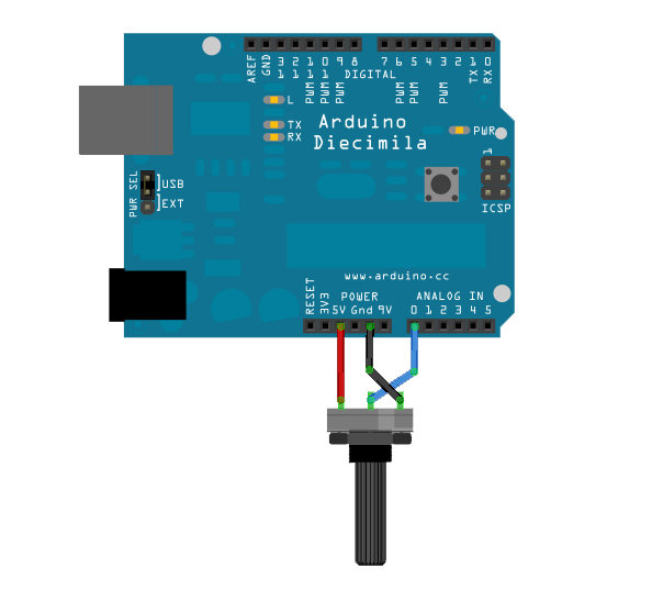
- Potentionmeter, or photocell, or pressure-sensitive resistor. Some analogue sensor.
Here's the circuit: 
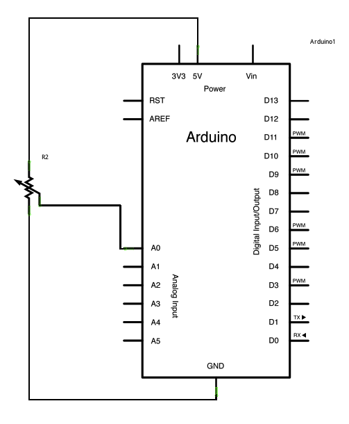
And the schematic: 
/*
  Graph

 A simple example of communication from the Arduino board to the computer:
 the value of analog input 0 is sent out the serial port.  We call this "serial"
 communication because the connection appears to both the Arduino and the
 computer as a serial port, even though it may actually use
 a USB cable. Bytes are sent one after another (serially) from the Arduino
 to the computer.

 You can use the Arduino serial monitor to view the sent data, or it can
 be read by Processing, PD, Max/MSP, or any other program capable of reading
 data from a serial port.  The Processing code below graphs the data received
 so you can see the value of the analog input changing over time.

 The circuit:
 Any analog input sensor is attached to analog in pin 0.

 created 2006
 by David A. Mellis
 modified 9 Apr 2012
 by Tom Igoe and Scott Fitzgerald

 This example code is in the public domain.

 http://www.arduino.cc/en/Tutorial/Graph
 */

void setup() {
  // initialize the serial communication:
  Serial.begin(9600);
}

void loop() {
  // send the value of analog input 0:
  // println prints the value and a newline character.
  Serial.println(analogRead(A0));
  // wait a bit for the analog-to-digital converter
  // to stabilize after the last reading:
  // Increase this delay to 500 (0.5 sec) if you want a more
  // reasonable data rate.
  delay(2);
}
Example 2
Now for a more elaborate code. Based on Dimmer.
Hardware needed:
- Arduino
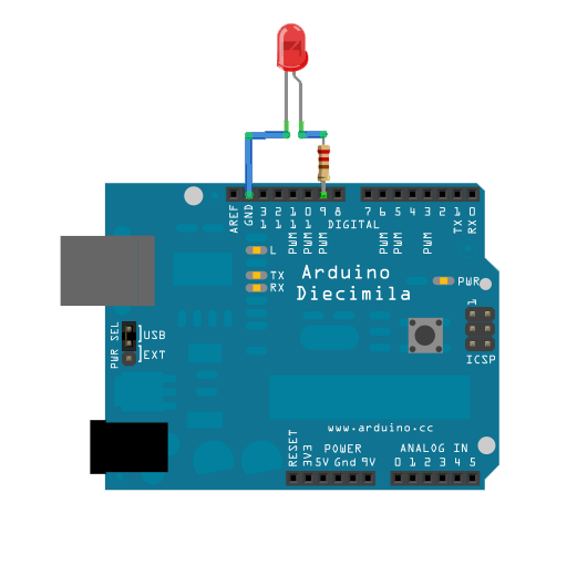
- LED
- 220 Ohm resistor
Setup: 
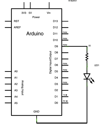
Circuit diagram: 
/*
  Dimmer

 Demonstrates the sending data from the computer to the Arduino board,
 in this case to control the brightness of an LED.  The data is sent
 in individual bytes, each of which ranges from 0 to 255.  Arduino
 reads these bytes and uses them to set the brightness of the LED.

 The circuit:
 LED attached from digital pin 9 to ground.
 Serial connection to Processing, Max/MSP, or another serial application

 created 2006
 by David A. Mellis
 modified 30 Aug 2011
 by Tom Igoe and Scott Fitzgerald

 This example code is in the public domain.

 http://www.arduino.cc/en/Tutorial/Dimmer

 */

const int ledPin = 9;      // the pin that the LED is attached to

void setup()
{
  // initialize the serial communication:
  Serial.begin(9600);
  // initialize the ledPin as an output:
  pinMode(ledPin, OUTPUT);
}

void loop() {
  byte brightness;

  // check if data has been sent from the computer:
  if (Serial.available()) {
    // read the most recent byte (which will be from 0 to 255):
    brightness = Serial.read();
    // set the brightness of the LED:
    analogWrite(ledPin, brightness);
  }
}