Contents
Navigation
Current Amplification & Voltage offsetting
There are two final additions to the circuit before it will be capable of driving a speaker:
- - we need it to be able to supply a larger current, i.e., it needs to be able to drive a large load. - the sine wave amplitude has a 2.5V DC component that needs to be removed.
Circuit Diagrams
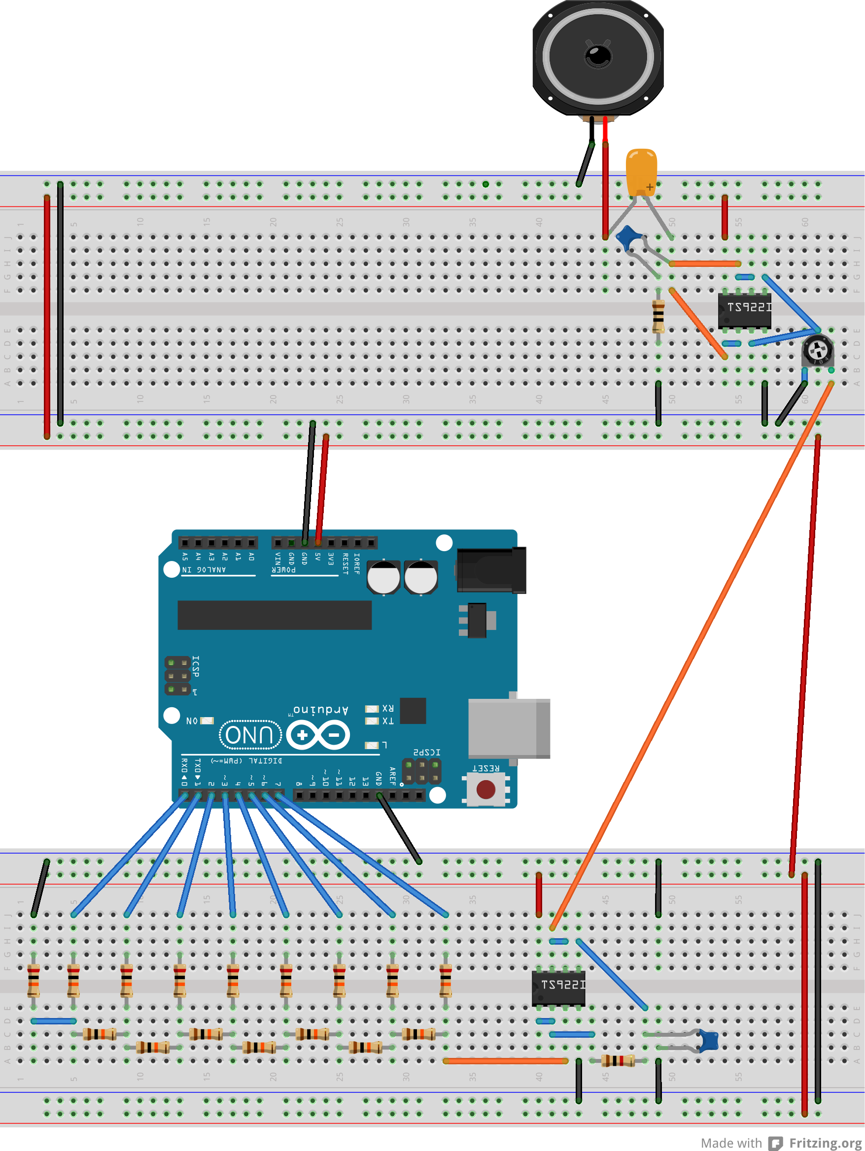
This circuit includes the speaker. It's a fairly complex circuit so please follow the breadboard view closely. You will require the extra empty space on the second breadboard for the final part of the experiment when we make the Light Theremin.

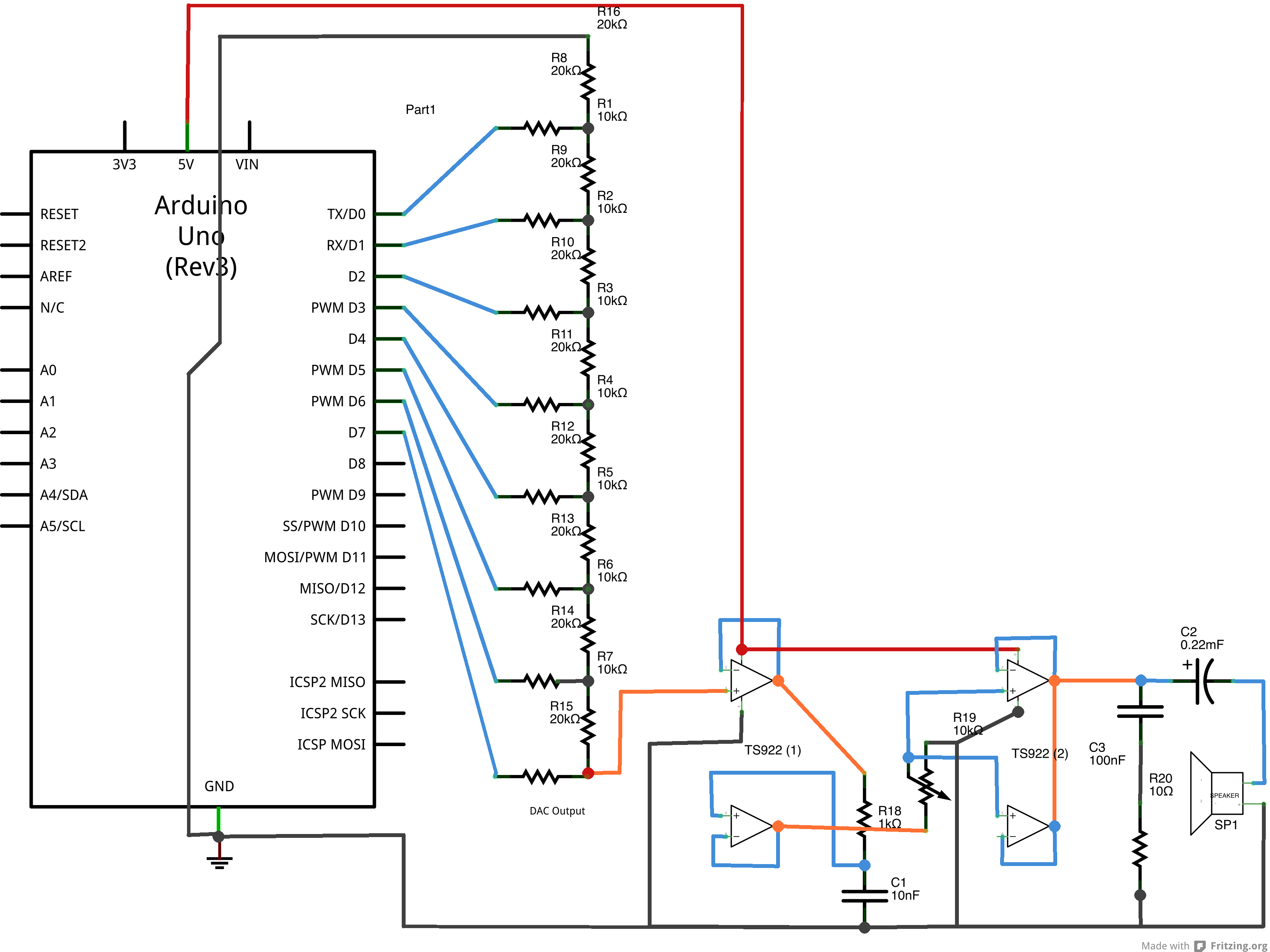
And here is the schematic view: 
And the Fritzing file is here. You may find it useful to view this file for this circuit as it can show you the interconnections between various parts more clearly.
Tip
It will help if you can place all components on a single breadboard. Try it only if you are comfortable with breadboards as the resulting circuit will have a lot of wires and will therefore be complex to debug.
Current amplification
We have used the second TS922IN op-amp as a current amplifier. Our DAC produces a 5V output which is high enough for most applications. But to drive a load like a speaker we require a sizable amount of current flow. Each op-amp can source about 80mA of current. So we use two in parallel to produce 160mA. Notice we have (yet again) used the unity-gain voltage-following setup for the op-amps.
DC Offset
We have one more issue to deal with before sending the waveform to the speaker: at present it oscillates about 2.5V. That is, the amplitude of the wave goes from 0V to (nearly) 5V. This is an AC waveform superimposed on a 2.5V DC signal. What we need to do is remove the DC component so the wave oscillates from -2.5V to 2.5V. We use the large 220$\mu$F capacitor to achieve this. A capacitor will always block the DC component in a signal. We need a large capacitor to handle large variations in the AC component without clipping.
The RC bridge before the 220$\mu$F capacitor is present to suppress high frequency noise. The time constant for this circuit is $T = 10^{-6}$ s, which corresponds to a frequency of 1 MHz. You will notice that there is no appreciable change in the sound output if the RC bridge is disconnected. But keep it there as circuits are prone to high frequency noise that may damage sensitive components.
Tasks
Construct the circuit. Sample the waveform just after the current amplification (before the DC offset) and after the 220$\mu$F capacitor. You should see effect of the offset. Make sure this is the case.
Important Task:
Take a screen-shot of the wave before and after offset. Use both channels of the oscilloscope so that both waves are on the screen at the same time.
An important quantity of any wave-generating device is its frequency range. Before proceeding to the light theremin, we will determine the frequency-range of the complete DAC (after buffering, filtering, amplification and DF-offsetting). This is an important step as the choices we have made in the various components in the circuit will effect the frequency range. It is also a difficult step as, so far, the only way we have of controlling the frequency of the sine wave is to change the delay value in the program. A reasonable range of delay values is 1$\mu s$ to around 100$\mu s$. It cannot be less than 1$\mu s$ with standard Arduino commands (it is possible to go lower using low-level assembly, but we will not go into this here).
Important Task:
What frequencies do these delay values correspond to?
Why is a delay of 100$\mu s$ a reasonable maximum value? What happens to the waveform for larger delays? Observe it on the oscilloscope.
Important Task:
Vary the delay from 1$\mu s$ to 100$\mu s$ and measure the frequency of the output wave using the oscilloscope. Compare this with the expected frequency calculated using:
$\begin{equation} f_{\rm expected} = 1/(N\times \tau), \end{equation}$
where $N$ is the number of samples (usually 100 but see the program) and $\tau$ is the delay in seconds. $f_{\rm expected}$ will be in Hz.
Plot $f_{\rm expected}$ versus $f_{\rm observed}$ on a log-log plot. Ideally we'd have a linear plot, but it will not be linear.
What is the frequency range of your wave-form generator?
Important Tasks:
Before going on the the next and last part of the experiment, you need to determine the range of delays that result in acceptable sine waves. Determine the largest and smallest delay (in $\mu$s) that results in reasonable sounds. What frequencies do these delays correspond to?
If we wanted to increase this range what would we need to change? What limits the range?
This ends the wave-form generation using a DAC. We have come a long way and are now set for the Theremin, but before going there, if you have time, this is a good place to play around with your circuit. Does the volume control work? Do your waves sound reasonably pleasing to the ear? What does a ramp wave sound like? There's a lot you can do with this device. But do this only if you have time!!!
