Navigation
Smoothing the waveform using an RC filter
The buffered DAC output is now usable (with small loads) but the waveform is too jagged to result in a pleasant sound: a common problem with all digitised waveforms. In this part of the experiment we will construct a low-pass filter to suppress the high-frequency steps in the waveform.
Since we are now interested in the actual waveform, we will need to use the sine-code without probes and calls to the serial monitor. We must not use calls to print to the serial monitor in real wave generation as these calls introduce large delays in the code.
Important
Tasks:
Upload the sine code to the Arduino.
- Visualise the buffered DAC output on an oscilloscope.
- Zoom onto a single wave period: can you see the steps in the waveform?
- How many steps are there?
- Are the number of steps the same as the number of //samples// used in the code?
The purpose of a low pass filter is to smooth out the output of the DAC in order to reduce noise. By using a low pass filter on the signal, we can smooth out the "steps" in the waveform while keeping the overall shape of the waveform intact. We will use an RC filter to achieve this: a resistor and a capacitor in series to ground. Connect the resistor to the incoming signal and the capacitor to ground, the signal coming from the junction between these two components will be low pass filtered. We will send the filtered signal into another buffer circuit (use the second op-amp in the TS922IN package for this) to protect the filtered signal from any loads further down in the circuit.
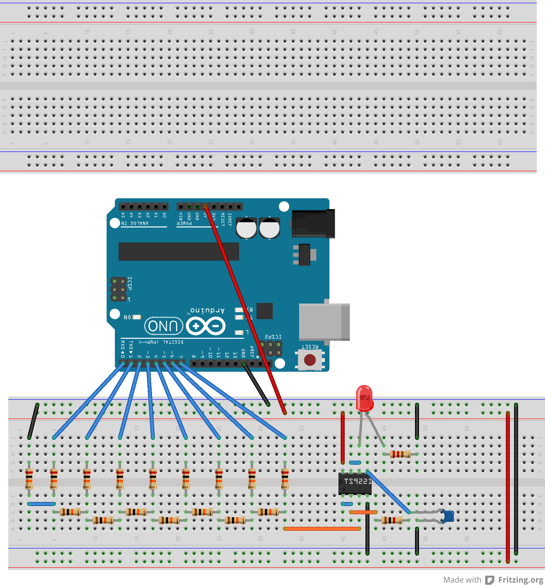
The breadboard diagram for the RC filter is as follows: 
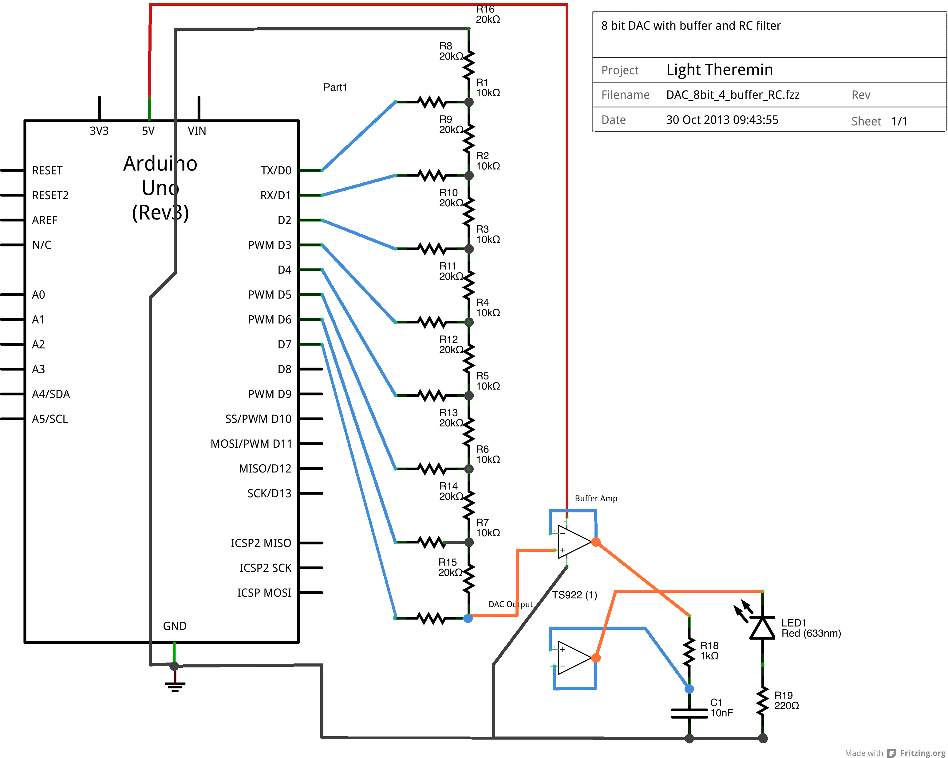
And here is the schematic view 
Finally, you will find the Fritzing file of the DAC with RC filter here.
What we need to do is determine the value of the capacitance and resistance needed to make an appropriate RC filter. This can be done using the following equation: \begin{equation}
- f_{\rm cutoff} = 1/(2 \pi RC)
\end{equation} where $R$ is the value of the resistance and $C$ the capacitance. For a cutoff frequency of 20 kHz (a reasonable limit) and a resistance of 1 k$\Omega$, we get $C = 8 \times 10^{-9}$ F or 8 nF. Round this off to 10 nF.
Important
Tasks:
- Build and test the above RC circuit.
- Analyse the waveforms before the RC stage and after the RC stage using the oscilloscope. What is the difference?
- What happens to the filtered wave if the capacitance is increased?
- Change the delay in the sine code to increase the frequency of the wave.
How do different capacitances effect the resulting waveform? Try out 0.1$\mu$F and 1$\mu$F capacitors. Is there a frequency at which these capacitors begin to result in a relatively recognisable sine wave?
