Contents
Navigation
Digital to Analogue Converter (DAC)
DAC Theory
A digital to analogue converter takes a series of digital inputs (a string of 1s and 0s, in our case there will be 8 of them like 10011001) and converts it into an analogue output. You see DACs in every digital audio device (MP3 players, CD players) as these all store music in digital form, but need to drive a speaker with an analogue signal. Hence the need to convert the digital data into an analogue signal.
Here's an example of how digitization works (figures from the Wikipedia article on DACs). To digitize an analogue signal like a wave we sample it at a typically fixed frequency (taken to be sufficiently high so that we do not hear artifacts due to the sampling) and save the samples in digital form: 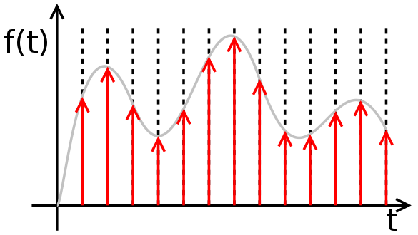 The DAC does the reverse: given the samples in digital form, re-create the analogue waveform:
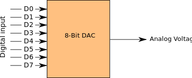
 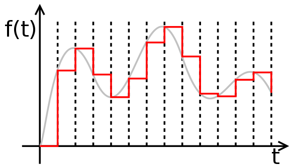 Of course, this is approximate. The steps will always be present, but as long as they are small enough, they may be smoothened out. To make them small enough we need to be able to sample accurately and use a large number of bits to represent the signal. For example, if we use only 4 bits to sample the waveform, we will have a resolution of only $2^4 = 16$ levels. With 8 bits the number of levels we can represent increases to $2^8 = 256$ levels. This is still not good enough for a commercial audio system, but it will be good enough for this experiment. Our goal is to build an 8-bit DAC that accepts sequences of 8 binary numbers (a byte) and outputs an analogue representation of that sequence:
Tip
Binary Numbers and Bits
We usually use Decimal numbers in our calculations. Computers use Binary numbers. Each binary number consists of a sequence of bits. These are 0s and 1s. A sequence of 8bits is called a Byte. In this experiment we will work with bytes.
How do we count in binary? Here is a sequence of binary numbers and their decimal equivalents (I've used 4bit sequences for conveneince). The subscripts indicate the number system in use: $2$ means binary, and $10$ means decimal.
$\begin{eqnarray*} 0000_{2} & = & 0_{10} \\ 0001_{2} & = & 1_{10} \\ 0010_{2} & = & 2_{10} \\ 0011_{2} & = & 3_{10} \\ 0100_{2} & = & 4_{10} \\ 0101_{2} & = & 5_{10} \\ \end{eqnarray*}$
How do we convert from binary to decimal? Consider the binary number $(b_3 b_2 b_1 b_0)_{2}$. The rule for converting it to decimal is:
$\begin{eqnarray*} (b_3 b_2 b_1 b_0)_{2} & = & b_3 \times 2^3 + b_2 \times 2^2 + b_1 \times 2^1 + b_0 \times 2^0 \end{eqnarray*}$
Or, more generally, for the $n$-bit binary number:
$\begin{eqnarray*} (b_{n-1}\cdots b_2 b_1 b_0)_{2} & = & \sum_{i = 0}^{n-1} b_i \times 2^i \end{eqnarray*}$
On a computer a $1$ is represented as a HIGH voltage (5V on the Arduino) and $0$ as a LOW voltage (0V on the Arduino, though on some systems all that may be necessary is a //sufficiently// low voltage.
For more on binary numbers see the Wikipedia article.
Cool fact: if you counted in binary using your fingers you'd be able to count from 0 to 1023.
In our setup, we will use the Arduino Uno to set the digital pin values. This will be done in software. The DAC will be made of resistors in what is known as an R-2R network. You will find more information about R-2R networks on the links provided below.
If you are interested in learning how an R-2R network works have a look at these links:
DAC description by Alexander Scheeline from the Department of Chemistry at the University of Illinois at Urbana-Champaign. Very good resource and worth reading. Explains how the ladder works as a complex voltabe divider. In particular, see the description of R-2R networks.
The description given in the above article doesn't directly apply to our circuit. Though you will see why it does work, if you'd like to dig more into our circuit have a look at this article which uses Thevenin's Theorem to simplify a DAC similar to the one we use. I've placed a PDF file of this article here.
RECOMMENDED: Here's another good article by Alan Wolke on DACs and R-2R networks. I've placed a PDF file of this article here. This article explains in some detail how the R-2R network can be analysed and demonstrates how we obtain the output voltage of the DAC.
Resistor Ladder from the Wikipedia. This is a shorter article.
Note
Why give you all these references?
This is meant to be a //real world// experiment. You are guided through it, but you are not spoon-fed. The reasons why we do certain things in paritcular ways is sometimes found elsewhere. You should make an attempt to read the references, particularly the recommended one.
Parts
In the first part of the experiment we will use 5% resistors in the DAC. Subsequently we will re-construct it using 1% resistors.
- 9 20 kOhm resistors 5%/1% metal film
- 7 10 kOhm resistors 5%/1% metal film
- Arduino Uno
- wire jumpers
The actual values of the resistors may vary. What is important is that one set of resistors has resistances twice the other.
Circuit
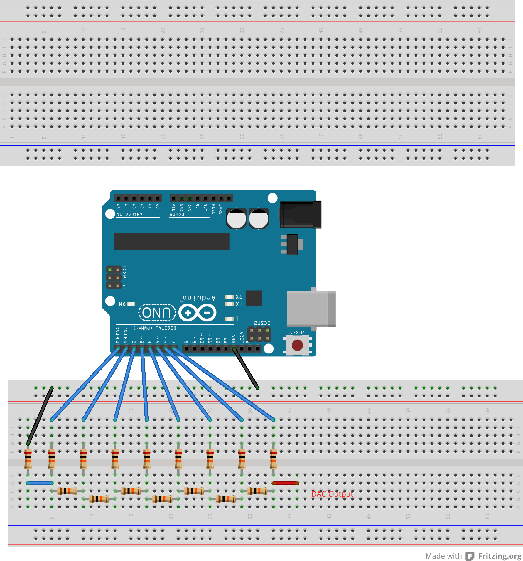
Here is a breadboard view of the DAC circuit. The second breadboard is included as we will place components here as the circuit develops. Also, there is a thin wire from one of the 20K resistors to ground. Ignore it. Click on the images for a larger view.
Warning
We will first use 5% resistors to construct the DAC. Make sure you use these and not the more accurate, 1% varieties! The 5% resistors may be 10KOhm and 22KOhm. If so, the resulting network will not be exactly an R-2R network, but that is OK. You will see the point of using these 5% resistors below.
And here is a schematic view:
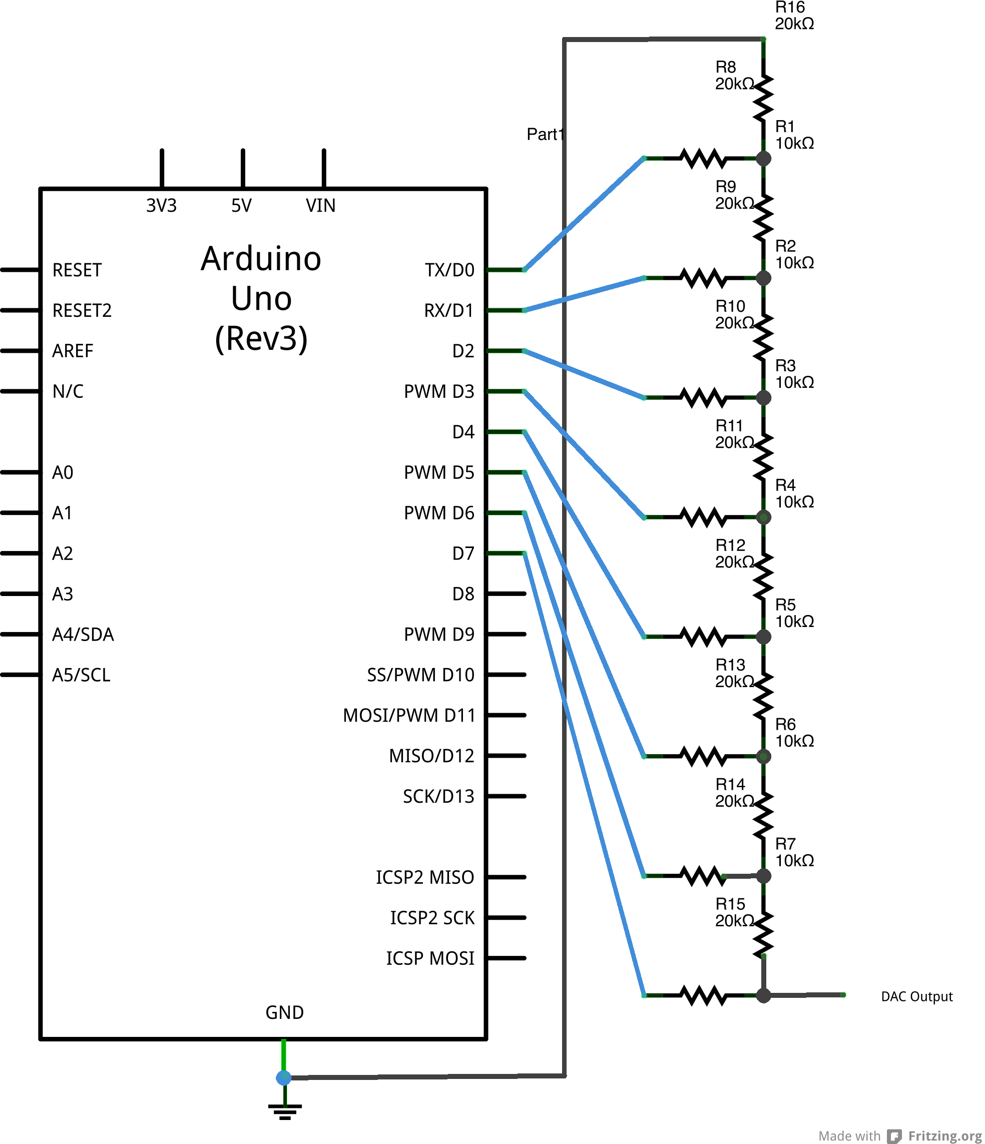
These circuit diagrams have been made with the Frit zing program. You can access the .
Tip
The Fritzing files (*.fzz) are editable. You can save these and edit them as you see fit. This could be useful for your own projects and for illustrating circuit diagrams for your report. But bear in mind that the edits are time-consuming so don't try to do it during the lab!
Programming the Arduino
Having constructed the DAC what we now need to do is program the Arduino to send a byte (8 bits) of data to the eight inputs of the DAC. Here is a code which does this:
/*
  DAC: Single byte
  A. J. Misquitta
*/

void setup(){
  //set digital pins 0-7 as outputs
  for (int i=0; i<8; i++){
    pinMode(i,OUTPUT);
  }
}

void loop(){
  digitalWrite(0, HIGH); // 1 : we start from the rightmost bit
  digitalWrite(1, LOW);  // 0
  digitalWrite(2, LOW);  // 0
  digitalWrite(3, LOW);  // 0
  digitalWrite(4, HIGH); // 1
  digitalWrite(5, HIGH); // 1
  digitalWrite(6, LOW);  // 0
  digitalWrite(7, HIGH); // 1
}
For details of Arduino sketches see the Arduino Getting Started page. If you haven't already gone over the material and examples on that page, please do so before proceeding. Let's look at what this sketch is up to. Recall that every Arduino sketch has a //setup// part and a //loop// part. The instructions in the //setup// part are executed only once, but the instructions in the //loop// part are executed till the device is switched off.
The first bit of code sets up digital pins 0 to 7 as outputs. We have used a //for// loop to do this:
void setup(){
  //set digital pins 0-7 as outputs
  for (int i=0; i<8; i++){
    pinMode(i,OUTPUT);
  }
}
This bit of code is equivalent to
void setup(){
  pinMode(0,OUTPUT);
  pinMode(1,OUTPUT);
  pinMode(2,OUTPUT);
  ...
  pinMode(7,OUTPUT);
}
but the former is clearly a lot more compact!
Next we enter the //loop// part in which we write the byte //10110001// to the DAC input pins. This is done by setting appropriate pins to HIGH (= 1) and others to LOW (= 0):
void loop(){
  digitalWrite(0, HIGH); // 1 : we start from the rightmost bit
  digitalWrite(1, LOW);  // 0
  digitalWrite(2, LOW);  // 0
  digitalWrite(3, LOW);  // 0
  digitalWrite(4, HIGH); // 1
  digitalWrite(5, HIGH); // 1
  digitalWrite(6, LOW);  // 0
  digitalWrite(7, HIGH); // 1
}
The general form of the digitalWrite (the upper case 'W' is essential!) is
digitalWrite(pin,VALUE);
where VALUE = HIGH or LOW.
Note
Question: What is the decimal value of the binary number 10110001?
This is all very well, but how would you read out the result of the DAC? We have a few options: we could use a multimeter to do the reading (do it), or an oscilloscope, or use the Arduino itself. Let's now explore the latter option.
Using the Analogue Input pins on the Arduino
The Arduino Uno includes 6 analogue input pins labeled 'A0' through 'A5'. Locate these on the board. Each of these can read and digitize an analogue signal from 0 to 5 Volts using a 10 bit Analogue to Digital converter (ADC). A 0V signal will correspond to Bin(0000000000) and a 5V signal to (11111111111). Notice that these are 10-bit binary numbers, so while a 0V signal will correspond to Dec(0), a 5V signal will be Dec(1023) ($1023 = 2^{10} - 1$). So what we will do now is to take the output of our 8-bit DAC and send it to port A0 on the Arduino. Then get the Arduino to read and digitize the input on port A0 and display it using the Serial Monitor. Here is the program that does this:
//DAC: Single byte
//A. J. Misquitta

/*
 * This program is free software; you can redistribute it and/or modify
 * it under the terms of the GNU General Public License as published by
 * the Free Software Foundation; either version 3 of the License, or
 * (at your option) any later version.
 *
*/

void setup(){
  //set digital pins 0-7 as outputs
  for (int i=0;i<8;i++){
    pinMode(i,OUTPUT);
  }
  pinMode(A0,INPUT);
  Serial.begin(9600);   // Output to Serial
  while (! Serial);     // Wait untilSerial is ready
  Serial.println("DAC: Single Byte!");
}

void loop(){
  digitalWrite(0, HIGH); // 1 : remember we start from the rightmost bit
  digitalWrite(1, LOW);  // 0
  digitalWrite(2, LOW);  // 0
  digitalWrite(3, LOW);  // 0
  digitalWrite(4, HIGH); // 1
  digitalWrite(5, HIGH); // 1
  digitalWrite(6, LOW);  // 0
  digitalWrite(7, HIGH); // 1
  //delayMicroseconds(50);//wait 50us if using an oscilloscope
  //delay(100);//wait 100ms if using a multimeter/serial port
  /*
    Having written the byte to the digital pins, we will read the
    output of the DAC using the analogue pin A0 of the Arduino Uno.
    The analogue pins are Analogue to Digital converters (ADC).
    Read the DAC output into variable DACout and write it to
    the serial port.
  */
  int DACout = analogRead(A0);
  if (Serial.available())
  {
    Serial.println(DACout);
  }
  delay(100);
}
Set up the circuit to read the DAC output on A0 and run this code. You will need to start the serial monitor to see the output of the code. The serial monitor may not start till you hit a key. After that you will see a string of numbers. They will fluctuate slightly.
Important
Task:
Question: Does the output at A0 correspond to the decimal value of the 8-bit input to the DAC? In the example above, we input the byte //10110001// to our 8-bit DAC. Earlier you were asked to figure out the decimal value of this byte. Does the reading on the serial port correspond to this value? If not, why not?
Hint: Our DAC has an 8 bit output while the ADC on the Arduino is a 10 bit converter. You may need to do a bit of scaling to get the expected value.
Important
Task:
Measure the output voltage of the DAC using a DMM (Digital Multimeter). Supply the DAC with 10 input values spanning the range of possible inputs (i.e., from 00000000 to 11111111). Record the DAC output voltage for each of these inputs.
Warning
Task:
Now re-construct your DAC using the more accurate 1% resistors.
Important
- Task:
Repeat the 10 measurements using identical inputs. Record the DAC output voltages.
Using Thevenin's theorem (see the article by Alan Wolke at Textronix) it can be shown that the output voltage of our DAC is given by
$\begin{equation}V^{\rm DAC} = 5 \times \left( \sum_{i = 0}^{7} b_i \left(\frac{1}{2}\right)^{(8-i)} \right) ~{\rm V} \end{equation}$
where the $b_i$ are the bits in the binary number. So, for example, for the binary number 10000011 we have
$\begin{equation} V^{\rm DAC}(10000011) = 5 \times \left( 1\times \left(\frac{1}{2}\right)^8 + 1\times \left(\frac{1}{2}\right)^7 + 0\times \left(\frac{1}{2}\right)^6 \\ ~~~~+ 0\times \left(\frac{1}{2}\right)^5 + 0\times \left(\frac{1}{2}\right)^4 \\ ~~~~+ 0\times \left(\frac{1}{2}\right)^3 + 0\times \left(\frac{1}{2}\right)^2 \\ ~~~~+ 1\times \left(\frac{1}{2}\right)^1 \right) ~ {\rm V} \end{equation}$
or $V^{\rm DAC}(10000011) = 5 \times ( 0.5117) ~ {\rm V} = 2.5586 ~ {\rm V}$
Important
Task:
Using the above formula, find the theoretical DAC voltages for your 10 sets of binary inputs. Compare these values with the two sets of results obtained above. Which set is closer to the theoretical values? Why do you think this might be the case?
Digital writes to PORTD
//The following explanation of PORTD has been lifted verbatim from Amanda's article.//
Now we know how to send a byte of data to the DAC and get an analogue output. From the introduction to digitization given above we know that to create a waveform all we need to do is send in a sequence of bytes to our DAC. Let's see how we could send the DAC two bytes:
  // 10110100
  digitalWrite(0, HIGH); // 1 : remember we start from the rightmost bit
  digitalWrite(1, LOW);  // 0
  digitalWrite(2, LOW);  // 0
  digitalWrite(3, LOW);  // 0
  digitalWrite(4, HIGH); // 1
  digitalWrite(5, HIGH); // 1
  digitalWrite(6, LOW);  // 0
  digitalWrite(7, HIGH); // 1
  // 00001111
  digitalWrite(0, LOW);  // 0 : remember we start from the rightmost bit
  digitalWrite(1, LOW);  // 0
  digitalWrite(2, LOW);  // 0
  digitalWrite(3, LOW);  // 0
  digitalWrite(4, HIGH); // 1
  digitalWrite(5, HIGH); // 1
  digitalWrite(6, HIGH); // 1
  digitalWrite(7, HIGH); // 1
This would work, but to generate a sine wave we would need a lot of bytes of data (the more, the smoother the waveform). Clearly this approach to sending data to the DAC is of limited value.
An alternative is to loop over the bits in each byte:
  seq = (1,0,1,1,0,0,0,1);
  for (int i = 0, i < 8; i++)
  {
    digitalWrite(i,seq(i)); // seq(i) = 0 ==> LOW & seq(i) = 1 ==> HIGH
  }
  seq = (0,0,0,0,1,1,1,1);
  for (int i = 0, i < 8; i++)
  {
    digitalWrite(i,seq(i)); // seq(i) = 0 ==> LOW & seq(i) = 1 ==> HIGH
  }
Can you see how this works? It is shorter, and could have made it even shorter by using a function call. But there is an even simpler way of transmitting bytes to our DAC: The Arduino allows us to write an entire byte to pins 0 to 7 via PORTD.
PORTD is simply short-hand for pins 7,6,5,4,3,2,1,0 (in this order). We can write an 8-bit binary number (i.e., a Byte) directly to pins 0 to 7 like so:
// Write the byte 10110001 to pins 76543210 in that order:
PORTD = B10110001;
Here the B in front of 10110001 says that the number is in binary form. We could write two bytes as follows: Writing to PORTD in Binary
PORTD = B10110001;
PORTD = B00001111;
This is clearly a much better option! The code is shorter and also more readable. We can see the bytes we are writing to the DAC. Additionally, the Arduino Atmel328 chip is able to write to all eight pins simultaneously and not sequently as was done when we used the digitalWrite() commands. Since PORTD has 8 pins on it (digital pins 0-7) we can send it one of $2^8 = 256$ possible values ($0-255$) to control the pins.
We could send the data to the DAC (via PORTD) in decimal form as follows:
PORTD = 177; // decimal form of 10110001
PORTD = 15;  // decimal form of 00001111
In the following pieces of code we send a value between 0 and 255 to "PORTD" when we want to send data to the DAC, it looks like this:
PORTD = 125;//send data to DAC
This is called addressing the port directly. On the Arduino, digital pins 0-7 are all on port D of the Atmel328 chip. The PORTD command lets us tells pins 0-7 to go HIGH or LOW in one line (instead of having to use digitalWrite() eight times). Not only is this easier to code, it's much faster for the Arduino to process and it causes the pins to all change simultaneously instead of one by one (you can only talk to one pin at a time with digitalWrite()).
For example, if we wrote the following line:
PORTD = 0;
it would set pins 0-7 LOW. With the DAC set up on pins 0-7 this will output 0V. if we sent the following:
PORTD = 255;
it would set pins 0-7 HIGH. This will cause the DAC to output 5V. We can also send combinations of LOW and HIGH states to output a voltage between 0 and 5V from the DAC. For example:
PORTD = 125;
125 = 01111101 in binary. This sets pin 7 low (the most significnat bit (MSB) is 0), pins 6-2 high (the next five bits are 1), pin 1 low (the next bit is 0), and pin 0 high (the least significant bit (LSB) is 1). You can read more about how this works here. To calculate the voltage that this will output from the DAC, we use the following equation:
- voltage output from DAC = [ (value sent to PORTD) / 255 ] * 5 V
so for PORTD = 125:
voltage output from DAC = ( 125 / 255 ) * 5V = 2.45V
The code below sends out several voltages between 0 and 5V and holds each for a short time to demonstrate the concepts described above. In the main loop() function:
  PORTD = 0;//send (0/255)*5 = 0V out DAC
  delay(1);//wait 1ms
  PORTD = 127;//send (127/255)*5 = 2.5V out DAC
  delay(2);//wait 2ms
  PORTD = 51;//send (51/255)*5 = 1V out DAC
  delay(1);//wait 1ms
  PORTD = 255;//send (255/255)*5 = 5V out DAC
  delay(3);//wait 3ms
The delay command is a new one. It causes the code to pause for the specified number of milliseconds (ms). So delay(1) causes a delay of 1 ms. This is OK for an ocsilloscope, but it is too short if we are using the ADC on the Arduino to sample the output of the DAC. In this case we need to multiply the delays by 100 or more. We will do this in the examples below.
DAC: Waveform generation
We will now send sequences of bytes to our DAC (using PORTD) to generate and visualise waveforms.
Square waves
The first example is a simple square waveform generation code:
/*
  Based on code by Amanda Ghassaei

  Square wave generation using the DAC

*/
void setup(){
  //set digital pins 0-7 as outputs
  for (int i=0;i<8;i++){
    pinMode(i,OUTPUT);
  }
}

void loop(){
  PORTD = 0;//send (0/255)*5 = 0V out DAC
  delay(2000);//wait 2ms * 1000 = 2s
  PORTD = 127;//send (127/255)*5 = 2.5V out DAC
  delay(2000);//wait 2s
  PORTD = 51;//send (51/255)*5 = 1V out DAC
  delay(1000);//wait 1s
  PORTD = 255;//send (255/255)*5 = 5V out DAC
  delay(3000);//wait 3s
}
Here we have increased the //delay//s to allow voltage measurements using a multimeter. When using the oscilloscope divite all delays by 1000 so that they are all in ms (rather than seconds).
With the longer delays you can read out the voltages produced by our DAC using a multimeter.
Important
Record the voltages you obtain. Do they correspond to the values you would have expected?
View the waveform on the oscilloscope. Measure the period and amplitudes of the wave. Are these what you'd expect? Include a printout of the waveform on the oscilloscope in your report.
Ramp Wave
Next we will try getting a ramp waveform:
//Ramp out
//by Amanda Ghassaei
//http://www.instructables.com/id/Arduino-Audio-Output/
//Sept 2012

/*
 * This program is free software; you can redistribute it and/or modify
 * it under the terms of the GNU General Public License as published by
 * the Free Software Foundation; either version 3 of the License, or
 * (at your option) any later version.
 *
*/

void setup(){
  //set digital pins 0-7 as outputs
  for (int i=0; i<8; i++){
    pinMode(i,OUTPUT);
  }
  pinMode(A0,INPUT);
  Serial.begin(9600);                        // Output to Serial
  while (! Serial); // Wait untilSerial is ready
  Serial.println("Waveform generation!");
}

void loop(){
  /*
    The waveform is produced by sending values 0 to 255 to PORTD
    in sequence. We need a delay between these values. If using
    an oscilloscope use a delay of 50 microsecs. If using the
    Serial Monitor increase this to 100 ms.
  */
  for (int a=0;a<256;a++){
    PORTD = a;    //send out ramp to digital pins 0-7
    // delayMicroseconds(50); //wait 50us if using an oscilloscope
    delay(100); //wait 100ms if using the serial port

    if (Serial.available())
    {
      int DACout = analogRead(A0);
      Serial.println(DACout);
    }
  }
}
Use either both the Serial port and the oscilloscope to view this wave form. As before, when viewing it on the oscilloscope reduce the delay to 1ms. Save a screen capture from the oscilloscope for your report.
Important
Task: Modify the program to create a zig-zag waveform.
Describe what you have done to achieve this. Try controlling the period of the waveform by adjusting the delay. When do you see the steps in the waveform?
Are the steps regular? They should be in an ideal DAC. If they are irregular, can you think of reasons why this may be the case?
To get higher frequency waveforms we need to replace //delay()// with the //delayMicroseconds()// command. This introduces delays in $\mu$s.
Important
Task:
Replace //delay()// by //delayMicroseconds()//. Use delays of around 10$\mu$s. Measure the frequency of the wave on the oscilloscope. Is it what you would expect?
Sine wave
Now for a sine wave. This is the most important waveform we will generate as it will form the basis for the light theremin. We will learn a few ways of generating sine waves and a few ways of visualising the results. We will also learn how to control the frequency of this wave.
We will make use of both the oscilloscope and the serial monitor to visualise waveforms.
Sine wave: For Oscilloscope
First for the simplest way of generating a sine wave:
Sine wave : simple example for oscilloscope
/*
  Simple sine waveform generation based on code by Amanda Ghassaei

  Use the oscilloscope to visualise the output of the DAC.
*/
void setup(){
  //set digital pins 0-7 as outputs
  for (int i=0;i<8;i++){
    pinMode(i,OUTPUT);
  }
}

void loop(){
  /*
    We will send to the DAC a sine wave centered around
     (127/255)*5 V = 2.5V
    That is, the wave should be symmetrically place.
    The delay controls the frequency of the wave.
    Change the delay values to see what happens to the waveform.

    The number of samples (= 100) sets the quality of the wave.
    The more the samples, the smoother the wave, the fewer the
    samples, the coarser the wave.
  */
  int samples = 100;
  for (int t=0; t<samples; t++){   //increment "t"
    PORTD = 127+127*sin(2*3.1415926*t/samples);
    delayMicroseconds(50); //wait 50us : for oscilloscope
  }
}
Measure the frequency of the waveform from the DAC using the oscilloscope. What do we expect it to be? We can work this out as follows:
Let $\tau$ be the time delay (50 $\mu$s in the above example).
And let $N$ be the number of samples (= 100 above).
The period of the wave is $T = N \times \tau$. This would be $100\times50\times 10^{-6} = 0.005$ s.
So the frequency of the wave is $f = 1/T = 200$ Hz.
Does this agree with what the oscilloscope measures?
Important
Task: View the waveform outputed by the DAC using an oscilloscope. Change the delay in the range 1 to 1000$\mu$s. Choose 10-15 delays to cover this range fairly evenly. What is the highest frequency we can generate? Make a plot of the observed frequency versus the expected frequency obtained using the above formula. Is it linear? Is there a value of the delay for which they are close?
It may be advantageous to make a log-log plot.
Sine wave : Getting to higher frequencies
We clearly have a problem with the above method of generating sine waves. There is a simple reason why we cannot get high frequency sine waves from the above code: the Arduino is a relatively slow microcontroller and it takes it many clock cycles to calculate a sine function. So each sine calculation introduces a fairly long delay in the code, and this, in turn, increases the period of the wave; that is, it's frequency decreases!
Luckily there is a way around this limitation: we pre-compute the sine wave form and store the results in an array - that's an ordered list of numbers like a vector (only longer). Here's how we do this:
More efficient Sine wave generation
//Sine out with stored array
//by Amanda Ghassaei
//http://www.instructables.com/id/Arduino-Audio-Output/
//Sept 2012

/*
 * This program is free software; you can redistribute it and/or modify
 * it under the terms of the GNU General Public License as published by
 * the Free Software Foundation; either version 3 of the License, or
 * (at your option) any later version.
 *
*/

byte sine[] = {127, 134, 142, 150, 158, 166, 173, 181, 188,
195, 201, 207, 213, 219, 224, 229, 234, 238, 241, 245, 247,
250, 251, 252, 253, 254, 253, 252, 251, 250, 247, 245, 241,
238, 234, 229, 224, 219, 213, 207, 201, 195, 188, 181, 173,
166, 158, 150, 142, 134, 127, 119, 111, 103,  95,  87,  80,
 72,  65,  58,  52,  46,  40,  34,  29,  24,  19,  15,  12,
  8,   6,   3,   2,   1,   0,   0,   0,   1,   2,   3,   6,
  8,  12,  15,  19,  24,  29,  34,  40,  46,  52,  58,  65,
  72, 80,  87,  95, 103, 111, 119,};

void setup(){
  //set digital pins 0-7 as outputs
  for (int i=0;i<8;i++){
    pinMode(i,OUTPUT);
  }
}

void loop(){
  int samples = 100;
  for (int t=0; t<samples; t++){  //increment "t"
    PORTD = sine[t];
    delayMicroseconds(50); //wait 50us
  }
}
Does this code procude a sine wave with frequency 200 Hz? Check this.
Important
Task: Repeat the above exercise with this code. View the waveform outputed by the DAC using an oscilloscope. Change the delay in the range 1 to 1000$\mu$s. What is the highest frequency we can generate? Has it increased? Make a plot of the observed frequency versus the expected frequency obtained using the above formula. What is the frequency range possible with this code?
Sampling a sine wave using Python
Note
This is the Python code that generated the values used in the above code:


import math
for x in range(0, 100):
  print str(int(127+127*math.sin(2*math.pi*x*0.01)),)+str(","),

This is here for your information only. To run this code, save it to a file, say sine.py, and from the command line type

python ./sine.py

Ask someone for help if you'd like to see this working. One use for this code is that you could use it to sample any waveform which you could then use in the DAC. This is an example of sampling used in any digital musical instrument.
We are now in a position to generate sine waves for the theremin, but before proceeding we will look at a way of visualizing the waveform without an oscilloscope. Why do this? Well, the Arduino is meant to be a hobbist device (though it can be used for research projects too!). And most of us do not have an oscilloscope at home, so here we will see how we can sample the DAC waveforms without one!
